
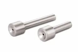
A sprue is the primary flow passage that transfers molten plastic from the injection molding machine nozzle into the mold feeding system. In a conventional mold, the melt typically flows through the sprue, runner, and gate before entering the mold cavity.
In some single-cavity molds, the sprue can feed the cavity directly. Its geometry affects melt flow, pressure loss, temperature loss, and the removal of the solidified sprue after molding.

What Is a Sprue in Injection Molding?
A sprue is the main flow passage between the injection molding machine nozzle and the runner system. It begins where the machine nozzle meets the mold and extends toward the runner or, in some designs, directly toward the cavity.
A conventional injection molding flow path can be simplified as:
Machine nozzle → sprue → runner → gate → cavity
A conventional runner system generally consists of the sprue, runners, gates, and cold slug well. These components work together to transfer molten plastic into the cavity and transmit injection pressure during filling and solidification.
What Does a Sprue Do?
The main functions of a sprue are to:
- Transfer molten plastic from the machine nozzle into the mold.
- Provide a flow path to the runner or cavity.
- Limit unnecessary pressure and temperature losses.
- Support consistent filling of the downstream feeding system.
- Allow the solidified sprue to be removed during mold opening and ejection.
The sprue is only one part of the filling system. Injection pressure and speed, melt temperature, material viscosity, runner dimensions, gate design, cavity geometry, and cooling conditions also affect filling behavior.
Types of Sprue in Injection Molding
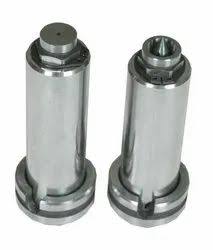
Sprue configurations are commonly considered within either conventional cold-runner or heated feeding systems.
Cold Sprue
In a conventional cold-runner mold, the plastic inside the sprue and runners cools and solidifies during the molding cycle. The solidified sprue and runner material are removed when the mold opens.
A cold sprue system generally offers:
- Relatively straightforward mold construction
- No dedicated heating elements in the conventional runner system
- Solidified sprue and runner material after each cycle
- The possibility of controlled regrind for suitable thermoplastic applications
A cold sprue does not inherently cause inconsistent filling. Filling problems are more likely when the sprue, runner, gate, process conditions, or material are poorly matched to the application.
Hot Sprue and Hot Runner Systems
A heated sprue or hot sprue arrangement keeps the relevant portion of the feeding system at an elevated temperature so that the polymer remains molten during the required stages of the molding cycle.
A broader hot runner system may include heated manifolds and hot nozzles. Its main advantage is reducing solidified runner material and, in suitable applications, improving material utilization.
The trade-offs include higher tooling complexity, temperature-control requirements, and additional maintenance considerations.
The choice between conventional cold-runner and heated systems depends on:
- Part geometry
- Polymer processing behavior
- Cavity count
- Production volume
- Material waste requirements
- Gate location and appearance
- Mold cost and maintenance requirements
A heated system is therefore not automatically preferable to a conventional cold-runner system.
Sprue Bushing and Nozzle Interface
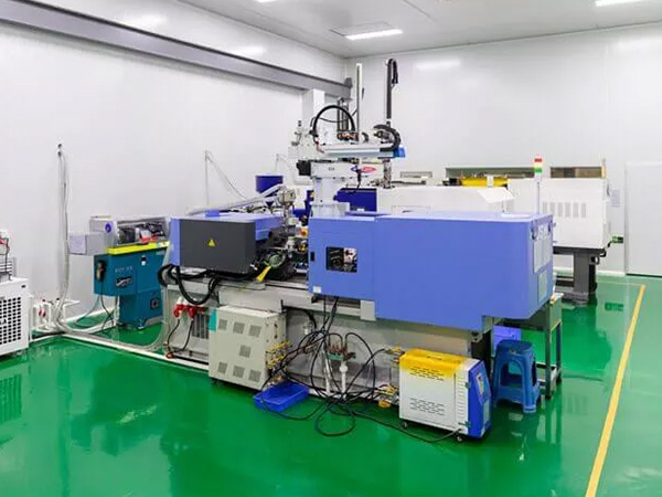
A sprue bushing, also called a sprue bush, is the replaceable mold component that forms the sprue passage and provides the interface between the injection machine nozzle and the mold.
The nozzle-contact area is exposed to repeated heat, pressure, and mechanical contact. Using a separate sprue bushing allows this wear-sensitive component to be manufactured and treated separately and replaced without replacing the surrounding mold plate. Pasted text
Sprue Bushing in Injection Molding
The sprue bushing should be positioned so that its centerline aligns with the injection machine nozzle. The nozzle and bushing also need compatible contact geometry to prevent leakage and maintain reliable material transfer. Pasted text
Nozzle and Sprue Bushing Fit
Injection machine nozzles commonly use a spherical contact surface. The corresponding recessed surface of the sprue bushing should be matched to the nozzle geometry.
The supplied mold-design reference gives the following values for a conventional sprue:
| Parameter | Reference value |
|---|---|
| Sprue small-end diameter | Nozzle diameter + 0.5–1 mm |
| Sprue bushing spherical radius | Nozzle spherical radius + 1–2 mm |
| Spherical seating height | 3–5 mm |
| Sprue taper | 2°–6° |
| Sprue length | Preferably ≤60 mm |
| Surface roughness | Ra < 0.8 μm |
These are reference values from the supplied mold-design material, not universal requirements for every injection mold. Actual dimensions should be matched to the injection machine, nozzle geometry, mold construction, polymer, and selected component specifications. Pasted text
Incorrect nozzle-to-bushing contact can allow molten plastic to leak at the interface. Poor alignment can also increase wear and interfere with consistent material transfer.
Basic Sprue Design Parameters
For conventional horizontal or vertical injection molds, the sprue is generally tapered rather than cylindrical. The taper helps the solidified sprue release from the mold during demolding. The supplied reference gives a 2°–6° taper angle for this type of mold. Pasted text
Sprue Diameter
The small end of the sprue is connected to the machine nozzle, so its diameter needs to be coordinated with the nozzle opening.
The supplied reference recommends a small-end diameter approximately 0.5–1 mm larger than the nozzle diameter. The larger end then increases according to the sprue length and taper.
The reference relationship is:
D = d + 2L tan(α/2)
where:
- D = large-end diameter
- d = small-end diameter
- L = sprue length
- α = sprue taper angle
These dimensions are starting points for design rather than universal specifications. Pasted text
Sprue Length
The sprue should generally be kept as short as practical.
A longer sprue increases the distance through which the melt travels and can increase pressure and temperature losses. It also increases the amount of solidified material in a conventional cold-runner system.
The supplied reference recommends keeping the main sprue length at 60 mm or less where practical. Pasted text
Sprue Surface Finish
The supplied reference gives a surface roughness of Ra < 0.8 μm for the sprue.
Surface finish works together with taper to support reliable release of the solidified sprue. The final requirement should be selected according to the polymer, mold material, geometry, and production conditions. Pasted text
Cold Slug Well and Sprue Removal
A cold slug well helps capture relatively cold material that can form near the injection nozzle during the interval between molding cycles.
The material near the nozzle can be cooler than the required melt temperature. If this material enters the feeding system or cavity at an unfavorable point in the cycle, it can contribute to molding problems.
The cold slug well provides space for this material and can also help retain the solidified sprue and runner material on the appropriate mold half during mold opening. The supplied reference describes cold slug wells as serving both cold-material containment and demolding functions. Pasted text
The appropriate cold slug well configuration depends on the polymer, mold structure, and ejection method. Options described in the supplied reference include Z-shaped pullers, reverse-taper configurations, ring-groove designs, and ejector-related arrangements. Pasted text
How Is the Solidified Sprue Removed?
After the plastic in a conventional sprue cools and solidifies, it must separate from the sprue bushing and remain with the intended mold half during opening.
The sprue taper and surface finish contribute to reliable release. A suitable cold slug well, sprue puller, or other retention feature can also help control removal of the sprue and runner system.
If the sprue sticks in the bushing, the molding cycle can be interrupted and manual intervention may be required.
How to Choose a Sprue Design
Sprue design should be selected together with the machine nozzle, material, part geometry, runner system, and production requirements.
| Design factor | Main sprue consideration |
|---|---|
| Machine nozzle | Nozzle diameter, spherical radius, contact geometry, and alignment |
| Material | Processing temperature, viscosity, thermal behavior, and flow resistance |
| Part geometry | Flow length, wall thickness, gate location, and appearance requirements |
| Cavity count | Runner arrangement and flow distribution between cavities |
| Production volume | Conventional cold runner versus potentially more complex heated systems |
| Part appearance | Sprue or gate location and resulting surface vestige |
| Demolding | Taper, surface finish, retention, and ejection method |
For medical components, sprue design should also be considered alongside material selection, dimensional requirements, mold design, process control, and the broader requirements of medical device injection molding.
What Is a Sprue Mark?
A sprue mark is the visible vestige or surface feature that can remain where the sprue or direct sprue gate connects to the molded part.
Its appearance depends on the feeding configuration, gate location, removal method, polymer, and part requirements. Where appearance or functional surfaces are important, the sprue location should be selected with the expected vestige and post-molding operation in mind.
A sprue mark is therefore not automatically a molding defect. Its acceptability depends on the component’s design and surface requirements.
Frequently Asked Questions
What Is the Difference Between a Sprue, Runner, and Gate?
A sprue transfers molten plastic from the injection machine nozzle into the mold feeding system.
A runner distributes the melt from the sprue toward one or more gates.
A gate is the restricted passage through which the molten plastic enters the mold cavity.
In a conventional system, the relationship is:
Nozzle → Sprue → Runner → Gate → Cavity
What Is a Sprue Bushing?
A sprue bushing is a replaceable mold component that forms the sprue passage and provides the interface between the injection machine nozzle and the mold.
Its contact geometry, opening diameter, alignment, taper, material, and surface condition contribute to reliable sprue operation.
What Is a Cold Slug Well?
A cold slug well is a mold feature that captures relatively cold material near the beginning of the flow path so that it is less likely to enter the cavity at an unfavorable point in the molding cycle.
It can also help retain the solidified feeding system on the intended mold half during mold opening.
What Is a Sprue Mark?
A sprue mark is the visible vestige left where the sprue or direct sprue gate connects to the molded component.
Its size and appearance depend on the feeding configuration, location, removal method, material, and part requirements.
What Does Sprue Mean as a Waste Material?
The word sprue can refer both to the flow passage inside the mold and to the solidified plastic material that remains in that passage after molding.
In a conventional cold-runner process, the solidified sprue is separated from the molded component after ejection. For suitable thermoplastic materials, it may sometimes be processed as regrind, subject to material controls and product requirements. Pasted markdown
Can Sprue Material Be Recycled?
Some thermoplastic sprue and runner material can be reground and reused under controlled conditions.
Whether this is appropriate depends on the polymer, processing history, contamination risk, allowable regrind level, and product requirements. Medical molding applications require particular attention to material control before regrind is introduced into production.
Conclusion
A sprue is the primary flow passage that transfers molten plastic from the injection molding machine nozzle into the mold feeding system. In a conventional system, it works with the runner and gate to deliver material to the cavity.
Reliable sprue design requires more than selecting a passage diameter. Taper, length, nozzle interface, sprue bushing, surface finish, cold slug management, and demolding all need to be considered together with the material, part geometry, cavity layout, and production requirements.
For medical injection molding projects, SeaSkyMedical can support related plastic injection molding and mold-design requirements where sprue, runner, gate, and material considerations need to be evaluated as part of the complete mold.