Introduction
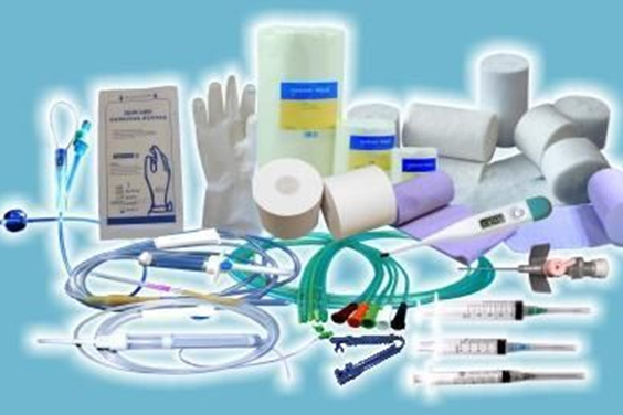
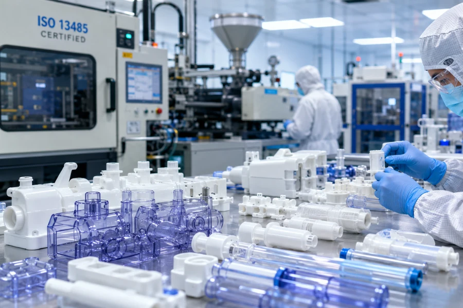
Medical injection molded components must demonstrate their safety, functional integrity, and consistency before being released for clinical applications or patient use. Establishing quality metrics involves more than post-production inspection; it requires integration of design, process validation, production, and continuous monitoring to ensure reliable outcomes. Compliance with standards such as ISO 13485 for quality management, FDA QSR 21 CFR Part 820, and ISO 14971 for risk management provides the framework for defining acceptable quality thresholds, and partnering with an ISO-certified provider like SeaSkyMedical ensures these standards are maintained across all manufacturing stages, from material selection to cleanroom production.

Dimension One: Process Validation and Capability Metrics
IQ / OQ / PQ Three-Stage Validation
Process validation in medical plastic injection molding is commonly structured into three sequential phases, each designed to confirm that equipment, processes, and outputs meet predefined quality criteria.
Installation Qualification (IQ)
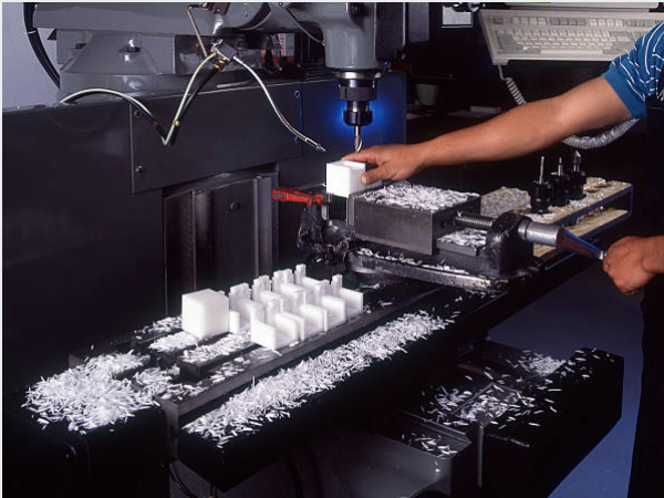
IQ verifies that all equipment, tooling, and ancillary systems are installed according to specifications. Key elements include checking calibration certificates, confirming utilities (electrical, compressed air, water) compliance, validating environmental conditions such as temperature, humidity, and cleanroom class, and verifying software and access controls. Documented maintenance and calibration plans are also established to support reproducible operations. This phase often collaborates closely with CNC plastic machining capabilities for precise component control.
Operational Qualification (OQ)
OQ defines the process parameter window, identifying the upper and lower limits for critical variables such as melt temperature, injection pressure, injection speed, holding pressure, and cooling time. This phase incorporates challenge testing—for example, power interruptions or emergency stops—to confirm that the system responds predictably, and ensures all alarms and safety mechanisms function properly. The validated operating ranges provide a reliable basis for consistent part production.
Performance Qualification (PQ)
PQ demonstrates that the injection molding process consistently produces parts that meet all specifications under standard production conditions. Multi-batch and multi-shift runs are monitored with sampling for dimensional, functional, and visual inspection, while process capability indices (Cpk) quantify stability and reproducibility. Documented PQ results serve as evidence for regulatory compliance and operational reliability. For highly precise features, micro injection molding or medical insert molding techniques may be applied to critical components.

Process Capability and Monitoring
Cpk measures process centering and variation, with ≥1.33 considered acceptable and ≥1.67 recommended for critical safety, mating, or sealing features. Key operational indicators such as OEE, first-pass yield, and on-time delivery rates (OTD) are tracked continuously. Re-validation is triggered by significant equipment relocation, mold maintenance, material changes, or on scheduled intervals, while FMEA and CAPA processes address potential failures proactively.
Dimension Two: Visual and Surface Quality Metrics
Surface Classification
Medical parts are evaluated based on Class A, B, and C surfaces, reflecting their visibility and functional significance:
| Class | Description | Requirements |
|---|---|---|
| A | Most visible surfaces under normal use | No visible defects; no flash, ejector pin marks, or scratches |
| B | Exposed but less prominent | Minimal defects allowed with quantitative limits |
| C | Contact or hidden surfaces | Functionally acceptable, no safety hazards |
Inspection Conditions
Visual inspection is performed at 30 cm for 3–5 seconds, extending to 50 cm for 3–7 seconds if uncertainty arises, using factory-standard fluorescent lighting (~1000 lux) with observer vision ≥0.7, and assessing both perpendicular and 45° angles from above and below. Inspection may leverage secondary operations such as assembly or packaging checks.
Acceptable Defect Limits
| Defect Type | A Surface | B Surface | Notes |
|---|---|---|---|
| Flash | Not allowed | Limited on non-critical areas; must be smooth | Must not detach or contaminate |
| Sink Marks | No visible depressions | Same as A | Cannot impair fit or seal |
| Scratches | ≤8 mm length, ≤0.05 mm width | ≤10 mm length, ≤0.1 mm width | Transparent parts require stricter control |
| Black Spots/Discoloration | ≤2 positions, <0.4 mm² each; separation >100 mm | ≤3 positions, <0.5 mm² each | Avoid logos/critical areas |
| Ejector Pin Marks | Not allowed | Not allowed | C surfaces ≤0.05 mm depth, no burrs |
| Gate Vestiges | Flat and smooth | ≤0.5 mm for assembly-required, ≤1.5 mm non-critical | Must not affect function |
Other considerations include short shots, weld lines, and silver streaks, which must be controlled to maintain structural strength and aesthetics. These inspections can be supported by medical device assembly processes.
Dimension Three: Dimensional and Geometric Tolerances
Standard Tolerances
Dimensional limits are defined according to part size, with tighter tolerances for critical mating features:
| Size (mm) | Tolerance (± mm) |
|---|---|
| 0–10 | 0.05 |
| 10.1–50 | 0.10 |
| 50.1–100 | 0.15 |
| 100.1–200 | 0.20 |
| >200 | 0.25 |
Critical features may require fine tolerances (±0.02–0.05 mm) matched to tooling capability and Cpk.
Allowable Warpage
- Base support surfaces: ≤0.3 mm
- Mating faces: ≤0.3 mm
- Sealing features (e.g., O-rings): ≤0.1 mm
Tolerance stack-up analysis ensures assemblies function correctly even when multiple components contribute to cumulative variation.
Dimension Four: Design Prerequisites for Quality
Material Selection and Wall Thickness
Material choice affects flow, shrinkage, thermal stability, and mechanical performance, and is critical in material selection for medical plastics. Recommended wall thickness ranges help minimize defects such as short shots and sink marks:
| Material | Recommended Wall Thickness (mm) |
|---|---|
| ABS | 1.14 – 3.56 |
| PC | 1.02 – 3.81 |
| PEEK | 0.51 – 5.08 |
| PP | 1.02 – 3.81 |
| POM | 0.76 – 3.05 |
Uniform wall thickness and smooth transitions (fillets or chamfers) reduce stress concentration and warpage.
Draft Angles
- Smooth surfaces: 1–2° per side
- Light texture: 3°
- Heavy texture: ≥5° (or add 1.5° per 0.025 mm texture depth)
Ribs and Bosses
- Rib thickness ≤0.5–0.6× wall thickness; height ≤2.5× wall; fillet at rib base
- Boss diameter ≤0.6× wall thickness; fillet radius 0.25–0.5× wall
Gate and Ejector Pin Placement
Gates should be on non-critical or hidden areas, minimizing visible weld lines. Ejector pins should be on C surfaces or ribs, with even force distribution to prevent deformation or marking. This stage can involve mold making and free mold/tool design services for optimized tooling.
FAQ
Q1: What quality certifications are required for medical injection molded parts?
A1: ISO 13485 is mandatory; FDA QSR 21 CFR Part 820 applies for U.S. markets; cleanroom production follows ISO 14644; materials must have biocompatibility evidence (ISO 10993).
Q2: Are IQ/OQ/PQ required for all medical parts?
A2: Class II/III critical components require full validation; Class I or low-risk parts may follow simplified procedures but should maintain documentation.
Q3: What Cpk values define acceptable parts?
A3: Standard Cpk ≥1.33; for safety-critical or mating features, Cpk ≥1.67.
Q4: Are flash defects acceptable?
A4: No flash may detach and contaminate the cleanroom; minor flash allowed if smooth and ≤0.05 mm.
Q5: What ejector pin marks are permissible?
A5: None on A/B surfaces; for C surfaces ≤0.05 mm, without burrs or sharp edges.
Q6: How is warpage defined as acceptable?
A6: Flatness or warpage ≤0.3 mm; sealing features ≤0.1 mm; function must remain unimpaired.
Q7: How can sink marks be prevented in design?
A7: Maintain uniform wall thickness; rib thickness ≤0.6× wall; avoid isolated thick areas; optimize gate placement and cooling via plastic injection molding flow analysis.
Q8: Are there special requirements for transparent parts?
A8: Visible weld lines, gas traps, silver streaks, or scratches are not tolerated; SPI A1/A2 polish and increased draft are often required under cleanroom conditions.
Q9: Is PQ required for low-volume batches?
A9: Synchronous validation may be used with enhanced first-piece inspection; documentation must show batch consistency.
Q10: What if dimensional tolerances exceed the standard table?
A10: Define fine tolerances for critical features, coordinate with suppliers, and apply tooling adjustments or secondary operations if necessary.