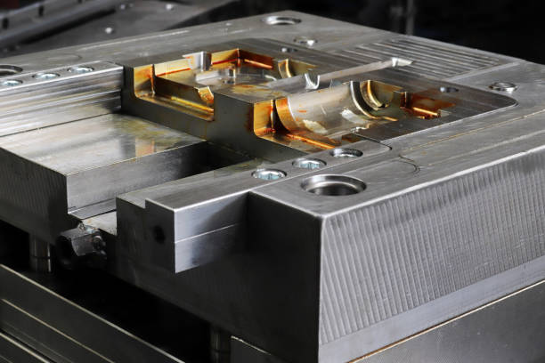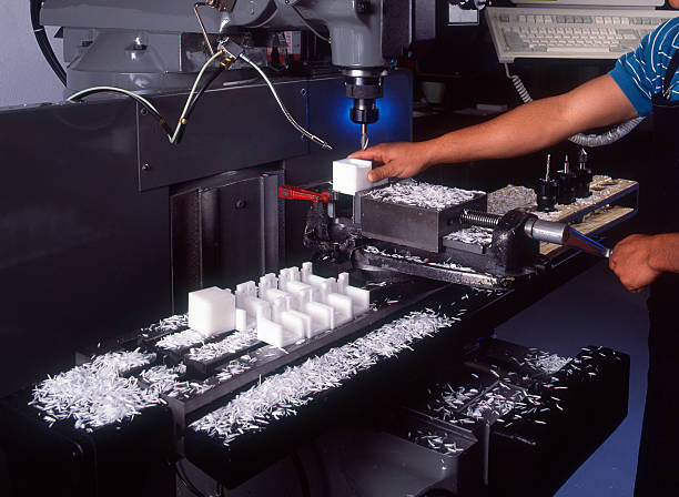
Injection molding gates control how molten plastic enters a mold cavity. Their design affects filling, packing, gate vestige, part appearance and the amount of post-molding work required.
Different gate types suit different part geometries, materials and production requirements. Understanding their structures, advantages and limitations helps manufacturers evaluate tooling designs and select a suitable gating approach before production begins.
This guide explains nine commonly discussed injection molding gate configurations, how gate type and placement affect part quality, and which factors matter when choosing a gate for a plastic component.
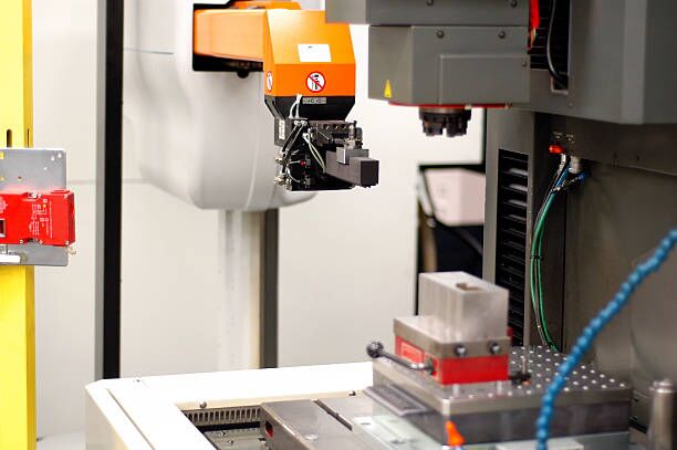
What Is an Injection Molding Gate?
An injection molding gate is the opening through which molten plastic enters a mold cavity from the runner system or a hot runner nozzle. In a conventional cold-runner mold, the gate connects the runner to the cavity. In a hot-runner mold, the melt may enter through a heated nozzle or a valve-controlled outlet.
The gate is a critical part of the mold’s filling system. Its cross-sectional area, length and location influence melt velocity, pressure loss, shear conditions and the time available for packing before the gate freezes.
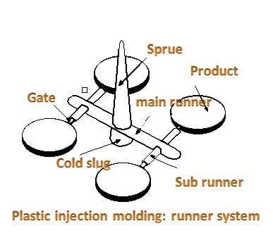
The gate also determines where the molded part separates from the runner or where a residual gate mark remains. Depending on the design, gate removal may require manual trimming, automated separation or no conventional cold-runner removal.
A gate that is too restrictive may cause excessive pressure loss, incomplete filling or premature gate freeze. An oversized gate may leave a more prominent vestige, require additional trimming and prolong cooling in some applications. The appropriate dimensions depend on the resin, part geometry, processing conditions and tooling design.
Gate selection should account for four primary considerations:
- Part geometry, wall thickness and flow length
- Resin viscosity, thermal stability and processing characteristics
- Acceptable gate vestige, surface finish and degating method
- Tooling cost, production volume and cavity layout
9 Types of Gates in Injection Molding
Injection molding gate terminology varies among manufacturers and engineering references. Some names describe the gate’s shape or location, while others refer to its separation mechanism or hot-runner configuration. The nine categories below retain the subject coverage of the original article while clarifying important differences between related designs.
Direct or Sprue Gates
A direct gate, often called a sprue gate, feeds molten plastic directly from the sprue into the mold cavity. It generally has a relatively large flow passage compared with a small restrictive gate.
Direct gates can reduce flow resistance and support packing through a relatively large gate section. They are often considered for single-cavity molds and parts with substantial sections or long flow paths, depending on the material and part geometry.
Advantages
- Relatively low flow resistance
- Straightforward mold construction
- A larger gate section can support packing and delay gate freeze
Limitations
- The gate can leave a prominent mark or residual projection.
- Concentrated entry flow may create localized stress or cosmetic defects.
- Removing the sprue may require additional trimming or machining.
Direct gates can be appropriate when flow and packing requirements take priority over minimizing the gate mark. Their suitability depends on the component’s geometry, resin and surface requirements rather than part size alone.
Edge Gates
An edge gate introduces molten plastic at the parting line, usually through a channel connecting the runner to the side or edge of the part. Its cross-section is commonly rectangular, although the final geometry depends on the mold design.
Edge gates are widely used because they are relatively easy to machine, inspect and modify. Their location also makes manual or automated gate removal comparatively straightforward.
Advantages
- Relatively simple and economical tooling
- Flexible positioning along a suitable parting line
- Gate dimensions can be adjusted to influence filling and packing
Limitations
- A visible gate vestige may remain after trimming.
- Poor placement or sizing can contribute to weld lines, jetting or other flow-related defects.
- A restrictive gate may limit filling or freeze before packing is complete.
Tab gates and film gates are related configurations, but they are not exact synonyms for every edge gate. A tab gate introduces melt through a tab-shaped section that can help manage localized flow and trimming effects. A film gate uses a broad, thin opening to distribute melt across a wider region.
The appropriate design depends on flow distribution, material behavior, part geometry and acceptable finishing operations.
Submarine Gates
A submarine gate, also called a tunnel gate, is a type of subgate that introduces melt through an angled or tapered passage, typically below the mold parting line.
Its geometry allows the molded part and runner to separate during ejection in suitable designs. This can reduce manual degating and support automated production.
Advantages
- Can reduce the visibility of gate marks on selected surfaces
- Can enable automatic gate separation
- Can support multi-cavity production when the runner and gate system are properly balanced
Limitations
- The narrow passage can increase pressure loss and restrict filling.
- The gate geometry requires careful machining and ejection design.
- Automatic shearing may place stress on the gate region or mold components.
- Resin properties and part geometry can limit suitability.
Submarine gates are often considered for components that require less visible gate marks or automated gate separation. They are not automatically suitable for every thick-walled or cosmetic part. Gate dimensions, filling requirements and material behavior at ejection must be evaluated together.
Cashew Gates
A cashew gate, also called a banana gate, uses a curved passage to introduce melt into the cavity from a less exposed location. It is related to tunnel-style gating, but its curved geometry distinguishes it from a conventional straight tunnel gate.
The design can allow the gate to reach a location that would be difficult to access with a straight passage. Depending on the mold layout, the gate and runner may separate during ejection.
Advantages
- Provides flexibility when selecting a less visible gate location
- Can support automatic degating in suitable designs
- Can help avoid placing the gate on a prominent exterior surface
Limitations
- Curved passages are more difficult to machine and maintain.
- The geometry can restrict the materials and dimensions that can be processed reliably.
- Ejection and gate separation must be validated to avoid damage or inconsistent trimming.
Cashew gates should not be treated as interchangeable with all edge gates or submarine gates. Their suitability depends on the actual flow path, gate location and separation mechanism.
Diaphragm Gates
A diaphragm gate is used primarily for parts with large circular or annular openings, such as certain cylindrical components. The gating arrangement distributes melt around the opening, helping promote more uniform circumferential filling.
The term describes a gating configuration rather than a valve mechanism made from a flexible membrane. The exact structure and separation method should be confirmed from the mold design because terminology can vary among engineering references.
Advantages
- Can support more uniform filling around circular geometries
- Can reduce the likelihood of a major weld line caused by melt fronts meeting across an opening
- Can help maintain concentricity in suitable part designs
Limitations
- The gate or diaphragm section may require post-molding removal.
- Removing the gate can require additional processing.
- The design must account for part geometry, wall thickness and acceptable finishing methods.
Diaphragm gates are most relevant when circumferential flow distribution is important. They should not be treated as synonymous with every ring gate or valve-gated system.
Hot Runner Valve Gates
A hot runner valve gate uses a heated nozzle and a mechanically controlled valve pin to regulate melt entry into the cavity. The pin opens to permit filling and closes to stop the flow at the gate.
Valve gating provides positive control over the opening and closing of the gate. It is often considered for production molds that require controlled filling, reduced gate vestige or coordinated injection across multiple cavities.
Advantages
- Controlled gate opening and closure
- Potentially small and consistent gate vestiges
- No conventional cold runner to remove when the system feeds the cavity directly
- Greater control over filling sequences in suitable multi-gate systems
Limitations
- Higher tooling and system costs than many conventional cold-runner arrangements
- Additional maintenance requirements for valve pins, actuators and heated components
- Greater system complexity and more demanding process control
Valve gates can be valuable for high-volume or demanding applications, but their benefits depend on part requirements, production volume and the cost of operating and maintaining the hot-runner system.
Hot Runner Thermal Gates
A thermal gate, often associated with an open hot-tip gate, uses a heated nozzle and controlled thermal conditions to maintain the melt near the cavity entrance. Unlike a valve gate, it does not use a valve pin to mechanically close the gate.
The heated nozzle helps keep the plastic molten until it enters the cavity. The gate then freezes or solidifies according to the resin and process conditions.
Advantages
- Eliminates the conventional cold runner when used in a suitable hot-runner arrangement
- Can reduce runner waste and associated handling
- Can support direct feeding for suitable part geometries
Limitations
- Requires careful thermal control and appropriate nozzle design.
- The gate can leave a visible mark or localized flow-related cosmetic defects.
- Heat-sensitive materials may require particular attention to residence time and temperature.
- Hot-runner tooling generally costs more than a comparable conventional cold-runner mold.
Thermal gates and valve gates should be distinguished by their shutoff mechanisms. Thermal gates rely on thermal conditions, while valve gates use a mechanical pin. The terms thermal gate and hot tip can vary by manufacturer, so the actual nozzle and gate structure should be confirmed before finalizing the classification.
Fan Gates
A fan gate is a broad gate that expands across the flow width toward the cavity. Its geometry distributes melt over a wider entry region than a narrow conventional edge gate.
Fan gates are often considered for wide, flat or thin-walled components where a more distributed flow front can help reduce localized flow concentration.
Advantages
- Distributes melt across a wider region
- Can improve filling uniformity for suitable flat geometries
- May reduce localized orientation effects and associated distortion compared with a poorly positioned narrow gate
Limitations
- Gate vestiges can be relatively large and difficult to remove cleanly.
- Flow may still be uneven if the gate depth, width or cavity geometry is poorly designed.
- The broad gate may require more material removal and finishing work.
Fan gates are useful when the part geometry benefits from a wide entry region. Their effectiveness depends on gate dimensions, runner dimensions, wall thickness and the flow characteristics of the selected resin.
Pin Gates
The term pin gate can refer to different designs in injection molding, so the intended structure should be confirmed on the mold drawing.
In a common three-plate mold arrangement, a pinpoint gate is a small, usually round opening that allows melt to enter the cavity. Its small cross-section can facilitate separation of the gate from the molded part when the mold opens.
Some manufacturing references also use pin gate or post gate for a different arrangement in which melt enters through a passage associated with an ejector-pin channel. That design has different tooling and ejection requirements and should not be confused with every pinpoint gate.
Advantages
- Can leave a small gate vestige
- Can support automatic gate separation in suitable mold designs
- Can be useful where a larger edge gate would interfere with appearance or function
Limitations
- Small openings can create high shear rates and significant pressure loss.
- The gate may freeze early, limiting packing.
- Three-plate or specialized gate arrangements can increase mold complexity.
- Resin viscosity, fillers, geometry and ejection conditions affect suitability.
Pinpoint gates can be useful when a small gate mark is important, but they are not automatically the best option for thin walls or precision parts. The actual gate geometry and location should be evaluated against the material and filling requirements.
The Importance of Gate Type and Gate Placement
Gate type and gate location must be evaluated together. A suitable gate design cannot compensate for every problem caused by poor placement, and the best location depends on part geometry, material and functional requirements.
For Injection Mold Gate Type
Gate type influences flow resistance, packing, gate vestige and the method used to separate the molded part from the runner. Selecting a gate therefore requires more than comparing its name or size.
For example, an edge gate may offer simpler tooling and convenient access for trimming, while a submarine gate may allow automatic separation in a suitable mold. A hot runner valve gate may provide greater control over melt entry but introduces additional tooling and maintenance requirements.
The choice should reflect the component’s functional needs, resin behavior, production volume and acceptable finishing operations.
For Gate Location in Injection Molding
Gate location affects flow length, filling sequence, weld-line position, air entrapment, packing and dimensional stability.
Placing a gate near a thick section may help deliver packing pressure where shrinkage compensation is needed, but it does not guarantee a defect-free part. The flow path, local wall thickness, cooling conditions and location of potential air traps must also be considered.
Likewise, a central gate may work well for a suitable symmetrical component but will not automatically produce uniform filling or minimal warpage in every design.
Gate placement should also account for the position of functional surfaces, sealing features, cosmetic areas and regions exposed to bending or impact loads. Mold-flow analysis can help evaluate filling patterns and potential defects when the part geometry or performance requirements justify it.
Key Points to Consider When Choosing an Injection Molding Gate
Choosing a suitable gate requires balancing part quality, manufacturing feasibility, tooling cost and production requirements. The following factors provide a practical starting point.
Suitable Gate Placement
The gate should support an appropriate filling pattern while limiting unacceptable weld lines, trapped air, jetting and localized stress.
Review the part’s geometry, wall-thickness distribution and flow paths before fixing the gate location. For parts with complex shapes or multiple flow paths, simulation and mold trials may be needed to validate the design.
Gates of Adequate Size
Gate dimensions affect flow resistance, pressure loss, shear conditions and gate-freeze timing. A restrictive gate may prevent adequate filling or packing, while an oversized gate can leave a more prominent vestige and increase finishing work.
The gate should be sized according to the resin, part dimensions, wall thickness, runner design and molding conditions. No single gate size or width-to-thickness ratio is suitable for every application.
Preferred Part Shape and Finish
Part geometry and surface requirements influence the choice of gate. A fan gate may suit a wide, flat component, while a direct gate may be acceptable for a part where a larger gate mark can be removed or placed on a noncritical surface.
Hot-runner valve gates may be considered where gate closure and vestige control are important, but the added tooling cost and maintenance requirements must be justified by the application.
Number of Injection Molding Gates
The number of gates depends on part size, geometry, flow length, material properties and the required filling pattern. A single gate may be sufficient for a simple component, while a larger or more complex part may require multiple gates.
Multiple gates can shorten individual flow paths, but they can also create additional weld lines where melt fronts meet. In multi-cavity molds, the runner and gate system must be designed to support consistent filling and packing across cavities.
The optimal number of gates should be determined through engineering review, and mold-flow analysis can help when filling balance or weld-line location is difficult to predict.
SeaSkyMedical Offers Medical Plastic Injection Molding Services
SeaSkyMedical supports medical plastic manufacturing projects through medical plastic injection molding, custom plastic molding and cleanroom injection molding.
Gate selection is one part of the broader mold-design process. For medical components, the design review should also consider material requirements, dimensional features, surface quality, assembly interfaces and the production controls needed for the intended application.
SeaSkyMedical also provides custom plastic injection molding and related manufacturing support. Discussing gate design during design for manufacturability (DFM) review can help identify tooling constraints before production tooling is finalized.
If you are evaluating a new medical plastic component or revising an existing mold, contact SeaSkyMedical to discuss your manufacturing requirements.
Conclusion
Injection molding gate selection affects filling, packing, gate vestige, part appearance and production cost. Direct, edge, submarine, cashew, diaphragm, hot-runner, fan and pin-style configurations serve different purposes, and their suitability depends on the specific structure rather than the name alone.
A sound gate design balances part geometry, material behavior, surface requirements, tooling complexity and production volume. Reviewing these factors early can help manufacturers identify design constraints and reduce avoidable changes during mold development.
For medical plastic components, gate selection should be considered alongside the wider mold design and manufacturing process to support the required part quality and production consistency